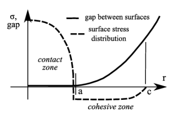
Derjaguin, Muller, and Toporov (DMT) – Adhesion theory Manoj Rajankunte Mahadeshwara March, 25 2025 Table of Contents Introduction Challenges DMT – Model Reference Introduction Adhesive contact mechanics has become an important area of study in nano- and biosciences. There are various methods developed over the past 75 years to address adhesive interactions in elastic contact problems. The emphasis is on connecting the local physical mechanisms of adhesion with macroscopic mechanical loading, with particular attention given to the contact equations. Adhesive contacts are crucial in various technological fields. Efficient manufacturing processes, like wafer cleaning in semiconductor technology, require tight control over surface contamination. Energy-efficient mechanical devices and reliable micromechanical systems depend on better management of friction and lubrication. Understanding key phenomena, such as particle immobilization or release in filtration, controlled positioning in reproduction devices, and the settling of bioorganisms on surfaces in health and biotechnology, is essential for further advancements. Challenges The first issue concerns the physical and chemical properties of surfaces and how two surfaces interact, along with how these interactions can be engineered through surface modification. The second issue addresses the impact of surface interactions on the overall mechanical response of a particle: for a given load, will the particle be captured, or can it be released? DMT – Model The Derjaguin, Muller, and Toporov (DMT) adhesion theory applies to elastic contact with adhesion between two locally spherical bodies under a normal force, without friction. It builds on the Hertz theory of contact but incorporates adhesion by assuming that the Hertz deformation profile remains unchanged by adhesion. The DMT theory is suitable for small values of the Tabor parameter, which corresponds to small radii, low adhesion, and high modulus materials. The DMT theory can also be applied to the adhesive contact of two elastically deformable spherical particles. It is generally considered suitable for small particles that have a high elastic modulus and low work of adhesion. Figure-1 The geometry of the DMT adhesive contact involves attractive interactions that act over the cohesive zone, which is an annulus with radius c surrounding the contact zone with radius a. The DMT model applies if c is greater than a. The pull-out force for the DMT theory is Fpullout = -2 πRw Where w is the adhesion energy and R is the contact radius As these more general results demonstrate, the DMT model depends on the interaction potential and the punch shape. Unlike the Derjaguin 1934 model, which assumes the pull-out force is controlled by the creation or destruction of the contact area, the DMT model suggests that the pull-out force is influenced by the motion of the punch in the long-range interaction potential. In this model, the adhesion energy w (which is coupled to the contact area) is not the relevant concept. Instead, the key parameter for adhesion is the amplitude of the interaction potential V₀. In the DMT theory, the punch displacement directly couples to the interaction potential. Figure-2 The schematic illustration shows the formation of a neck at the contact edge. In a thought experiment, an adhesionless contact is initially formed. When adhesion is introduced, the contact area begins to spread out (a). If a (negative) flat punch displacement is applied, it restrains the growth of the contact area, preserving the contact radius (b). Reference [1] Barthel, E., 2008. Adhesive elastic contacts: JKR and more. Journal of Physics D: Applied Physics, 41(16), p.163001. Manoj Rajankunte Mahadeshwara I am a postgraduate researcher at the University of Leeds. I have completed my master's degree in the Erasmus Tribos program at the University of Leeds, University of Ljubljana, and University of Coimbra and my bachelor's degree in Mechanical Engineering from VTU in NMIT, India. I am an editor and social networking manager at TriboNet. I have a YouTube channel called Tribo Geek where I upload videos on travel, research life, and topics for master's and PhD students.
发布时间:2025-03-25 TriboNet
A mechanical view of wear – The third body approach Manoj Rajankunte Mahadeshwara March, 14 2025 A mechanical view of wear – The third body approach Table of Contents Introduction Third Body approach Properties of the third body Boundary conditions Reference Introduction Surface roughness is an inherent property of any material, and it is established when two surfaces come in contact, it was assumed that these asperities were rounded than spiky. Further, the clean surfaces adhere to each other increasing adhesion hence artificial screening is performed on the industrial surfaces to avoid friction. Key challenges in this domain include predicting particle detachment during contact (relevant to both material science and mechanical engineering), understanding the mechanical conditions lead to screen destruction, and investigating the kinetics of screen regeneration. The behavior of detached particles is influenced by mechanical factors like velocity fields, while their composition and transformations fall under materials science. Third Body approach Any contact consists of two primary surfaces i.e. first body and an intermediate layer known as the third body. The third body can be defined in two ways: by its material composition, which differs from the first bodies, or by its role in accommodating velocity differences between the first bodies. Contacts are categorized as either “full,” where the space between first bodies is completely filled by the third body (e.g., in elastohydrodynamic lubrication), or “empty,” where the third body acts as struts to separate the first bodies, common in the initial rubbing of hard materials. Third bodies are introduced into the contact either tangentially (via the motion of the first bodies) or normally (through wear of the first bodies). Normal feeding involves wear, whereas tangential feeding helps prevent it. Lubricants, whether solid or liquid, are typically tangentially fed, while wear debris, such as from rubbing plastics, is fed normally. In multi-pass systems, both feeding methods can occur simultaneously, as newly formed debris mix with previously deposited particles, forming traces that are recirculated after being destroyed and reprocessed. Figure-1 Schematic showing variables which may influence wear when using the particle approach [2]. To achieve efficiency comparable to lubrication theory, the Third Body Approach (TBA) must predict load and friction for specific operating conditions and materials. For the simplest cases, such as full contacts, this requires: Understanding the properties and behavior of the third body. Analyzing how the third body interacts with the first bodies under load. Modelling the effects of these interactions on friction and wear. Accounting for the dynamics of third-body formation, destruction, and regeneration. Properties of the third body Understanding the rheological behaviour of the material acting as the third body is essential. This is straightforward when the third body is a material available in sufficient quantities, like a solid lubricant, as it can be studied directly. However, challenges arise when the third body is produced in minute amounts, such as from normal feed during the rubbing of plastics. In such cases, third bodies are extremely thin (less than 1 µm thick) and small in area, making them difficult to analyze with existing microrheometric techniques. Additionally, the behaviour of these third bodies cannot be directly inferred from the properties of the original material (first body), as compacted wear particles exhibit different characteristics. This complicates the understanding of third-body rheology and its relationship with the materials involved. Boundary conditions To fully understand the behaviour of third-body contacts, detailed information is needed about both longitudinal boundary conditions (entry and exit) and transverse boundary conditions (interfaces between the first body and third body). Unfortunately, very little data exists on these topics. Studies of two-body contacts indicate no clear relationship between tangential and normal stresses, and the situation is even more complex in three-body contacts. Observations suggest that particles in three-body interactions may adhere, roll, or slip on the counter face, but the exact boundary kinematics remain uncertain and are not yet well-defined. Developing a comprehensive theory of thin film mechanics that accounts for all possible rheological conditions is essential but challenging. This difficulty arises primarily from the high aspect ratio of the contact, where the film thickness is extremely small compared to the other contact dimensions. To address this, either generalized equations or advanced numerical discretization methods are needed. These approaches would provide an integrated understanding of contact behaviour, which is critical for making significant advancements in this field. Reference [1] Godet, M., 1984. The third-body approach: a mechanical view of wear. Wear, 100(1-3), pp.437-452. [2] Cowie, R.M. and Jennings, L.M., 2021. Third body damage and wear in arthroplasty bearing materials: a review of laboratory methods. Biomaterials and Biosystems, 4, p.100028. Manoj Rajankunte Mahadeshwara I am a postgraduate researcher at the University of Leeds. I have completed my master's degree in the Erasmus Tribos program at the University of Leeds, University of Ljubljana, and University of Coimbra and my bachelor's degree in Mechanical Engineering from VTU in NMIT, India. I am an editor and social networking manager at TriboNet. I have a YouTube channel called Tribo Geek where I upload videos on travel, research life, and topics for master's and PhD students.
发布时间:2025-03-14 TriboNet
Table of Contents Introduction Fiction of metal in hard on soft surface Effect of contaminating film with friction Effect of intermittent motion on friction Friction of metallic films Reference Introduction Kinetic friction is not merely a surface phenomenon but rather depends on the bulk properties of the interacting materials, such as their relative hardness and melting points. Experimental investigations indicate that friction primarily arises from shearing or adhesion of the softer material in contact with the harder surface. Even highly polished surfaces, which may appear smooth at the macroscopic level, possess microscopic irregularities that contribute to friction. The temperature rise at the interface is not the primary cause of friction, as friction can still occur at cold asperity contacts due to localized adhesion and welding under high pressure. However, when sliding occurs at high loads and speeds, the resulting temperature increase at the interface may give the impression that elevated temperatures directly cause higher friction. Importantly, this relationship does not imply that higher ambient (room) temperatures always lead to increased friction. Instead, the frictional behavior is influenced by temperature generated during sliding, which depends on parameters such as load and speed, rather than the initial room temperature. Fiction of metal in hard on soft surface The relationship between frictional force, contact area, and applied load has been extensively studied. Coulomb and Amontons formulated two key laws: (i) frictional force is independent of the apparent contact area, and (ii) it is proportional to the applied load. While these laws initially lacked a theoretical basis, studies on the real area of contact have provided explanations. With respect to the first law, various experiments revealed that the real area of contact between metals was measured using electrical conductance techniques. The findings revealed that contact occurs primarily at the summits of surface asperities, resulting in a real contact area that is significantly smaller and largely independent of the apparent contact area. This insight helps to explain why the frictional force is unaffected by changes in the apparent contact area, as the real contact area—and consequently the frictional force—remains consistent under similar loading conditions. Amontons’ second law, which states that frictional force is proportional to the applied load, initially posed challenges because it was assumed that the surfaces deformed elastically. Elastic deformation would predict the contact area, and thus the frictional force, to vary with the two-thirds power of the load, not linearly. However, conductivity measurements revealed that the surface deformation is predominantly plastic. Under plastic deformation, the material flows until the contact area becomes proportional to the applied load, resolving this inconsistency. Effect of contaminating film with friction Under most experimental conditions the metallic surfaces are covered with thin oxide layers and contaminating films. During sliding, these films are withered, allowing some metallic contact leading to penetration of surface irregularities through them. However, the adhesion and shear strength at these junctions are lower than those of pure metal. Earlier experiments confirm this, showing that removing surface films by outgassing in a high vacuum significantly increases friction (e.g., for nickel or tungsten, the coefficient of friction rises from ~0.3 to 6). Similarly, adding lubricants reduces contact and adhesion strength, though metallic adhesion still occurs as surface irregularities tear through the film. Lubricants significantly reduce the area of metallic seizure, primarily by lowering both the coefficient of friction and the shear strength at the junctions. Effect of intermittent motion on friction It has been studied that when any moving system has significant elastic freedom, this motion may become intermittent progressing via “stick-slip” behavior. This occurs because the kinetic friction during slipping is lower than the static friction during sticking. The type of sliding is strongly influenced by the properties of the metals and lubricant films, as well as the mechanical characteristics of the system, such as natural frequency, moment of inertia, and damping. Researchers have replicated these experiments, confirming that the elastic properties of the system play a key role in determining the motion. Stick-slip behavior is common in systems with elastic freedom or surfaces capable of slight elastic deformation, provided the surface and operating conditions are conducive to such motion. Friction of metallic films In earlier experiments, Amontons’ Law was observed because changes in the load naturally caused proportional changes in the area of contact, preventing independent variation of these factors. This limitation can be overcome by using a hard steel substrate coated with a thin layer of soft material, such as indium. When a hemispherical slider is placed on this surface and different loads are applied, the slider sinks into the indium until the load is supported by the underlying steel. Since the steel deforms minimally under further increases in load, the contact area between the slider and the indium remains largely unaffected, enabling independent control of load and contact area. Reference [1] Bowden, F.P. and Tabor, D., 1942. Mechanism of metallic friction. Nature, 150(3798), pp.197-199. [2] https://physics.aps.org/articles/v17/s120 Manoj Rajankunte Mahadeshwara I am a postgraduate researcher at the University of Leeds. I have completed my master's degree in the Erasmus Tribos program at the University of Leeds, University of Ljubljana, and University of Coimbra and my bachelor's degree in Mechanical Engineering from VTU in NMIT, India. I am an editor and social networking manager at TriboNet. I have a YouTube channel called Tribo Geek where I upload videos on travel, research life, and topics for master's and PhD students.
发布时间:2025-02-18 TriboNet
Table of Contents Introduction Wear Models Phenomenological approach Asperity Level Approach Rough surface Smooth surface Surface References Introduction Wear in dynamic systems significantly impacts performance, efficiency, operational costs, and safety. Predicting wear using computer simulations, empirical data, or theoretical frameworks is crucial for determining system reliability and durability. Haibo et al. [1] Reviewed wear modelling methods and depicted that wear modelling could be on macro, micro, or atomic scales. In light of this, wear modelling could be divided into a phenomenological approach or real contact conditions; the former utilizes physical understanding and experimental observation, i.e., macroscale level. In phenomenological technique, assumptions must be made, and empirical coefficients must be determined. Those models are constrained by their assumptions and lack generality, even though they provide accurate predictions for a specific range of operations and rely on the constraints of the empirical coefficients. Archard’s theory [2] and Rabinowicz’s criterion [3] These are examples of such models. The second method, such as asperities contact models, implements advanced numerical techniques to find the wear at micro- or atomic levels under relaxed assumptions and more realistic conditions; however, analytical models have been utilized for material and fracture estimation, and the actual surface characteristics may need to produce specific and accurate results. In the next section, microscale modelling techniques have been introduced. Wear Models Phenomenological approach An example of this approach is Archard’s wear model which is a famous model to evaluate adhesive wear. Theoretically, the Archard wear model estimates the adhesive wear volume of softer material. The model is named after Archard publicizes his work [2]; He said that the wear volume depends on the normal load and sliding distance and is inversely proportional to the hardness of the softer material. The wear volume (W) is defined as [4]: W = (K*P*S)/H – Equation-1 Where P is the normal force, S is the sliding distance, H is the softer material hardness, and is the dimensionless wear coefficient, and commonly used is the dimensional wear coefficient which is found experimentally and its value depending on lubricity condition and wear severity 1e-2 to 1e-9 [4] depending on the type of surface and lubricity condition. It’s commonly explained the wear rate is wearing volume per sliding distance (w) which is defined by [4]: w = (K * P) – Equation-2 Asperity Level Approach Asperity-level models for wear prediction offer valuable insights into wear phenomena, allowing for the estimation of wear volume and particle morphology. A prominent model developed by A. Greenwood and J. Williamson (GW model) [5], describes contact between rough, deformable surfaces, assuming that each asperity is loaded independently as shown in Figure 1. In this model, all asperities are hemispherical, with a constant radius of curvature distributed at different heights above mean surfaces. Figure-1 : GW model, contact of two rough surfaces [5] Numerical methods such as the Finite Element Method (FEM) and Boundary Element Method (BEM) are frequently employed to analyze complex dynamic systems. These methods transform model geometries into finite elements, making them particularly useful for studying rough surface contact—for example, Hu et al. [6] used asperity-level models to evaluate contact responses in such systems, and his FEM model is shown in Figure 2 which the rough surface has meshed with fine gird to capture the asperities contact. Figure-2 : Finite element mesh required for asperity level models as illustrated by Hu et al. [6] Rough surface Smooth surface Surface One of the critical advantages of asperity modelling is its ability to predict wear particle formation. H. Zhang and I. Etsion [7] utilized FEM to study spherical contact and the initiation of wear particles due to adhesive wear, finding the friction coefficient and wear volume for both elastic and plastic deformations. They also formulated wear particles resulting from these deformations as illustrated in Figure 3. Figure-3 : Wear particle formulation as different sliding instants as predicted by H. Zhang and I. Etsion model [7] At a smaller scale, atomic-level contact models have gained attention for providing detailed insights into contact phenomena. However, these models are limited to primary cases due to the need for extremely fine discretization. For instance, J. François et al. [8], using similar principles of asperity contact as depicted in Figure 4 and implemented the BEM mode, shown in Figure 5, to study asperity contact at the atomic scale and identified junction growth as a critical factor in wear particle formation. Despite the depth of understanding these models provide, they are constrained by the need for highly dense finite element models, which limit their broader application. Figure-4 : Schematic for atomistic simulations. (a) single-asperity surface (b) Interlocking asperities surface, J. François et al [8] Figure-5 : BEM model results which determined two wear mechanisms at the microscale level. (a) the plastic deformation without wear particle formulation. (b) the plastic deformation with wear particle formulation, J. François et al .BEM model [8] Moreover, asperity contact models require a failure criterion to simulate crack initiation and propagation for surface fracture. They also necessitate material models for plastic flow. Author: Shenouda Adel MSc in machine design References 1. Zhang, H., R. Goltsberg, and I. Etsion, Modeling Adhesive Wear in Asperity and Rough Surface Contacts: A Review. Materials (Basel), 2022. 15(19). 2. Archard, J.F., Contact and Rubbing of Flat Surfaces. Journal of Applied Physics, 1953. 24(8): p. 981-988. 3. Rabinowicz, E., The effect of size on the looseness of wear fragments. Wear, 1958. 2(1): p. 4-8. 4. Bhushan, B., Principles of Tribology. Modern Tribology Handbook. Vol. 1. 2001: CRC Press LLC. 5. Greenwood, J.A. and J.H. Tripp. The Contact of Two Nominally Flat Rough Surfaces. in Proceedings of the Institution of Mechanical Engineers. 1967. 6. Hu, G.-D., et al., Adaptive finite element analysis of fractal interfaces in contact problems. Computer methods in applied mechanics and engineering, 2000. 182(1-2): p. 17-37. 7. Li, M., G. Xiang, and R. Goltsberg, Efficient Sub-Modeling for Adhesive Wear in Elastic–Plastic Spherical Contacts. Lubricants, 2023. 11(5). 8. Molinari, J.-F., et al., Adhesive wear mechanisms uncovered by atomistic simulations. Friction, 2018. 6(3): p. 245-259. TriboNet Administration of the project
发布时间:2025-01-28 TriboNet
HomeWikiMechanism of Metallic Friction as described by Bowden and Tabor Mechanism of Metallic Friction as described by Bowden and Tabor Manoj Rajankunte Mahadeshwara January, 15 2025 Table of Contents Introduction Fiction of metal in hard on soft surface Effect of contaminating film with friction Effect of intermittent motion on friction Friction of metallic films Reference Introduction Kinetic friction is not merely a surface phenomenon but rather depends on the bulk properties of the interacting materials, such as their relative hardness and melting points. Experimental investigations indicate that friction primarily arises from shearing or adhesion of the softer material in contact with the harder surface. Even highly polished surfaces, which may appear smooth at the macroscopic level, possess microscopic irregularities that contribute to friction. The temperature rise at the interface is not the primary cause of friction, as friction can still occur at cold asperity contacts due to localized adhesion and welding under high pressure. However, when sliding occurs at high loads and speeds, the resulting temperature increase at the interface may give the impression that elevated temperatures directly cause higher friction. Importantly, this relationship does not imply that higher ambient (room) temperatures always lead to increased friction. Instead, the frictional behavior is influenced by temperature generated during sliding, which depends on parameters such as load and speed, rather than the initial room temperature. Fiction of metal in hard on soft surface The relationship between frictional force, contact area, and applied load has been extensively studied. Coulomb and Amontons formulated two key laws: (i) frictional force is independent of the apparent contact area, and (ii) it is proportional to the applied load. While these laws initially lacked a theoretical basis, studies on the real area of contact have provided explanations. With respect to the first law, various experiments revealed that the real area of contact between metals was measured using electrical conductance techniques. The findings revealed that contact occurs primarily at the summits of surface asperities, resulting in a real contact area that is significantly smaller and largely independent of the apparent contact area. This insight helps to explain why the frictional force is unaffected by changes in the apparent contact area, as the real contact area—and consequently the frictional force—remains consistent under similar loading conditions. Amontons’ second law, which states that frictional force is proportional to the applied load, initially posed challenges because it was assumed that the surfaces deformed elastically. Elastic deformation would predict the contact area, and thus the frictional force, to vary with the two-thirds power of the load, not linearly. However, conductivity measurements revealed that the surface deformation is predominantly plastic. Under plastic deformation, the material flows until the contact area becomes proportional to the applied load, resolving this inconsistency. Effect of contaminating film with friction Under most experimental conditions the metallic surfaces are covered with thin oxide layers and contaminating films. During sliding, these films are withered, allowing some metallic contact leading to penetration of surface irregularities through them. However, the adhesion and shear strength at these junctions are lower than those of pure metal. Earlier experiments confirm this, showing that removing surface films by outgassing in a high vacuum significantly increases friction (e.g., for nickel or tungsten, the coefficient of friction rises from ~0.3 to 6). Similarly, adding lubricants reduces contact and adhesion strength, though metallic adhesion still occurs as surface irregularities tear through the film. Lubricants significantly reduce the area of metallic seizure, primarily by lowering both the coefficient of friction and the shear strength at the junctions. Effect of intermittent motion on friction It has been studied that when any moving system has significant elastic freedom, this motion may become intermittent progressing via “stick-slip” behavior. This occurs because the kinetic friction during slipping is lower than the static friction during sticking. The type of sliding is strongly influenced by the properties of the metals and lubricant films, as well as the mechanical characteristics of the system, such as natural frequency, moment of inertia, and damping. Researchers have replicated these experiments, confirming that the elastic properties of the system play a key role in determining the motion. Stick-slip behavior is common in systems with elastic freedom or surfaces capable of slight elastic deformation, provided the surface and operating conditions are conducive to such motion. Friction of metallic films In earlier experiments, Amontons’ Law was observed because changes in the load naturally caused proportional changes in the area of contact, preventing independent variation of these factors. This limitation can be overcome by using a hard steel substrate coated with a thin layer of soft material, such as indium. When a hemispherical slider is placed on this surface and different loads are applied, the slider sinks into the indium until the load is supported by the underlying steel. Since the steel deforms minimally under further increases in load, the contact area between the slider and the indium remains largely unaffected, enabling independent control of load and contact area. Reference [1] Bowden, F.P. and Tabor, D., 1942. Mechanism of metallic friction. Nature, 150(3798), pp.197-199. [2] https://physics.aps.org/articles/v17/s120 Manoj Rajankunte Mahadeshwara I am a postgraduate researcher at the University of Leeds. I have completed my master's degree in the Erasmus Tribos program at the University of Leeds, University of Ljubljana, and University of Coimbra and my bachelor's degree in Mechanical Engineering from VTU in NMIT, India. I am an editor and social networking manager at TriboNet. I have a YouTube channel called Tribo Geek where I upload videos on travel, research life, and topics for master's and PhD students.
发布时间:2025-01-15 TriboNet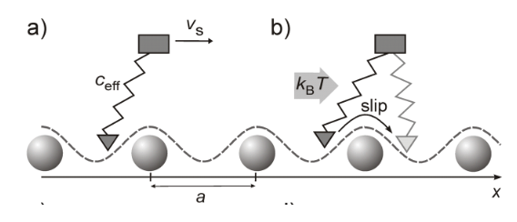
HomeWikiPrandtl-Tomlinson friction model Prandtl-Tomlinson friction model Manoj Rajankunte Mahadeshwara January, 8 2025 Prandtl-Tomlinson friction model Table of Contents Introduction Historical perspective Explanations Limitations of PT model Introduction The Prandtl–Tomlinson model was introduced in 1928 as a conceptual framework for single-atom contact friction, described as a point mass dragged over a sinusoidal potential by a spring. Although it remained largely overlooked for decades, recent experimental validations have demonstrated its relevance for contacts involving tens to hundreds of atoms. Today, the Prandtl–Tomlinson model is widely recognized as a highly insightful mechanical analogue for understanding atomic-scale phenomena at sliding interfaces. Historical perspective The field of nanotribology emerged in the late 1980s which was a significant leap in friction research by enabling the study of nanoscale contacts with tools like the atomic force microscope (AFM). Among its notable breakthroughs was the observation of individual atomic “hopping events” over a corrugated interface potential with atomic periodicity. These events revealed a “stick-slip” motion that revitalized interest in the Prandtl−Tomlinson (PT) model, an older conceptual framework. Historically, the PT model is often attributed to G. A. Tomlinson’s 1929 paper, which led to its alternate name, the “Tomlinson model.” However, the theory underlying the PT model was first presented in Ludwig Prandtl’s 1928 paper, which was initially inaccessible to much of the scientific community due to its publication in German. This oversight was corrected in 2012, when an English translation of Prandtl’s seminal work was published, finally clarifying its foundational role in modern nanotribology. Explanations The PT model today forms the cornerstone of our understanding of atomic-scale friction. In this model, a point mass moves over a periodic potential (illustrated in Figure 1), explaining a wide range of experimental observations. Figure-1 Schematic drawing illustrating the basic principles of the Prandtl−Tomlinson model. This schematics in Figure-1 a) and b) shows the basics of PT model, where a point mass is connected to a supporting body M via a spring with an effective spring constant ceff. The mass interacts with a periodic potential V(xt) with a periodicity ‘a’. During sliding, the supporting body M moves with a velocity vS in the x-direction. If the spring is sufficiently soft, the resulting motion exhibits characteristic “stick-slip” behavior. The point mass remains in a potential minimum (“stick”) until the spring tension reaches a critical value, at which point it jumps (“slips”) to the next minimum. The model also predicts temperature effects, which can be introduced by considering thermal oscillations of the mass. Figure-2 Graphs showing the scan position with lateral force wit changes in temperature Figure-2 c and d show at zero temperature (T=0K), the lateral force is a sawtooth-like function, with the mass jumping only when the critical force Fc for that potential and spring constant is reached. The lateral force is measured by tracking the spring tension as a function of the position of the supporting body M along the x-axis (“scan position”), which differs from the tip’s position xt. At higher temperatures, thermal activation allows the mass to jump at forces lower than Fc, due to thermal energy kBT (where kB is Boltzmann’s constant). As a result, the maxima of the lateral force and the overall frictional force decrease, and thermal noise becomes visible on the “rising leg” of the sawtooth pattern. Figure-3 ketch of a mechanical model designed by Prandtl The schematics of Figure 3 shows a macroscopic mechanical model created by Prandtl to demonstrate stick-slip behavior same as that of the atomic-scale model, illustrating the generalizability of the concept. The PT model has successfully explained friction phenomena across various systems, including flat surfaces, surfaces with different atom types, velocity and temperature dependence, atomic-scale steps, and ions in a trap. Notably, despite its origins as a single-atom model, the PT model provides intuitive explanations for many fundamental properties of dry friction. Limitations of PT model Extrapolation to Macroscopic Scale: While the PT model effectively explains friction at the atomic scale, it remains challenging to extrapolate its findings to larger, macroscopic contacts. Scaling up from nanometre-sized contacts to macroscopic rough interfaces has not yet been fully resolved. This limitation stems from the difficulty in translating atomic-scale behaviours into statistical models for complex, rough contact surfaces. Complexity of Real-World Surfaces: The PT model primarily addresses idealized, single-atom contacts. In real-world applications, surfaces are often non-ideal, featuring defects, surface steps, impurities, and varying chemical activities. These factors influence friction and are not adequately captured by the simple model, limiting its applicability to more complex systems. Structural Lubricity and Super-Lubricity: Although phenomena like “structural lubricity” or “super-lubricity” have been observed at atomic and small-scale contacts, the PT model does not fully account for how friction behaves in the presence of these phenomena when the contact area is large. The scaling of friction with contact area remains a significant challenge, and the model’s predictions for real, rough contacts are still incomplete. References: [1] Schwarz, U.D. and Hölscher, H., 2016. Exploring and explaining friction with the Prandtl–Tomlinson model. Acs Nano, 10(1), pp.38-41. [2] Tomlinson, G.A., 1929. CVI. A molecular theory of friction. The London, Edinburgh, and Dublin philosophical magazine and journal of science, 7(46), pp.905-939. [3] Tomlinson, G.A., 1928. LXVII. Molecular cohesion. The London, Edinburgh, and Dublin Philosophical Magazine and Journal of Science, 6(37), pp.695-712. Manoj Rajankunte Mahadeshwara I am a postgraduate researcher at the University of Leeds. I have completed my master's degree in the Erasmus Tribos program at the University of Leeds, University of Ljubljana, and University of Coimbra and my bachelor's degree in Mechanical Engineering from VTU in NMIT, India. I am an editor and social networking manager at TriboNet. I have a YouTube channel called Tribo Geek where I upload videos on travel, research life, and topics for master's and PhD students.
发布时间:2025-01-08 TriboNet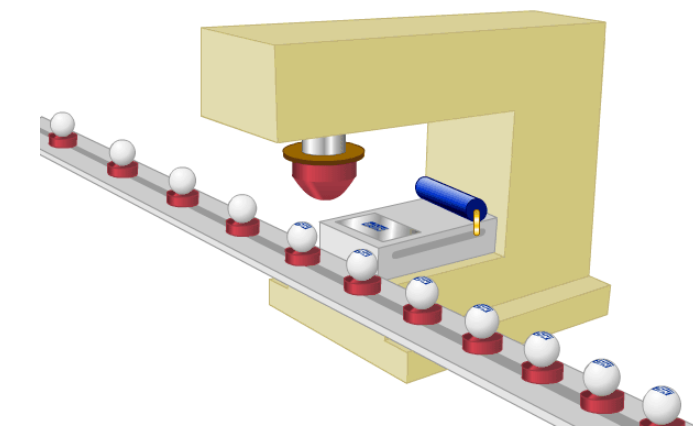
丝网印刷 是将丝织物、合成纤维织物或金属丝网绷在网框上,采用手工刻漆膜或光化学制版的方法制作丝网印版。现代丝网印刷技术,则是利用感光材料通过照相制版的方法制作丝网印版(使丝网印版上图文部分的丝网孔为通孔,而非图文部分的丝网孔被堵住)。印刷时通过刮板的挤压,使油墨通过图文部分的网孔转移到承印物上,形成与原稿一样的图文。丝网印刷设备简单、操作方便,印刷、制版简易且成本低廉,适应性强。丝网印刷应用范围广常见的印刷品有:彩色油画、招贴画、名片、装帧封面、商品标牌以及印染纺织品等。 移印 属于特种印刷方式之一。移印艺十分简单,采用钢(或者铜、热塑型塑料)凹版,利用硅橡胶材料制成的曲面移印头,将凹版上的油墨蘸到移印头的表面,然后往需要的对象表面压一下就能够印出文字、图案等。例如,手机表面的文字和图案就是采用这种印刷方式,还有计算机键盘、仪器、仪表等很多电子产品的表面印刷,都以移印完成。 曲面印刷 是先将油墨放入雕刻有文字或图案凹版内,随后将文字或图案复印到曲面上,再利用曲面将文字或图案转印至成型品表面,最后通过热处理或紫外线光照射等方法使油墨固化。 平版制程 由于平版印刷上的图文部分与非图文部分处于同一个平面上,在印刷时,为了能使油墨区分印版的图案部分还是非图案部分,利用油水分离的原理,首先由印版部件的供水装置向印版的非图文部分供水,从而保护了印版的非图文部分不受油墨的浸湿。然后,由印刷部件的供墨装置向印版供墨,由于印版的非图文部分受到水的保护,因此,油墨只能供到印版的图文部分。最后是将印版上的油墨转移到乳皮上,再利用橡皮滚轮与压印滚筒之间的压力,将乳皮上的油墨转移到承印物上,完成一次印刷,所以,平版印刷是一种间接的印刷方式。 烫印 (lettering),烫印,俗称"烫金",在我国已有很长的历史了。是指在精装书封壳的封一或封四及书背部分烫上色箔等材料的文字和图案,或用热压方法压印上各种凸凹的书名或花纹。 水转印技术 是利用水压将带彩色图案的 转印纸/塑料膜进行高分子水解的一种印刷。工艺流程包括水转印花纸的制作,花纸浸泡,图案转贴,干燥,成品。 IMD 即In-Mold Decoration(模内装饰技术)按其生产 加工方式可分为IMR和IML﹑IMF等几种。IMR (In-Mold Roller) :即模内墨转印是通过注塑将附著在薄膜上的油墨转印到产品外观面上﹐再通过模具开模过程揭开薄膜的一种模内装饰技术。ML (In-Mold Labeling) :置入贴标是通过人工或者是机械手将 印刷入裁减好的外观贴标置入模具后﹐通过射出成形使其附著到成品外观面上。 ML(IN MOLDING LABEL) IMR(IN MOLDING ROLLER) 机械抛光 是靠切削、材料表面塑性变形去掉被抛光后的凸起部分而得到平滑面的抛光方法,一般使用油石条、羊毛轮、砂纸等,以手工操作为主,特殊零件如回转体表面,可使用转台等辅助工具,表面质量要求高的可采用超精研抛的方法。超精研抛是采用特制的磨具,在含有磨料的工作液中,紧压在工件被加工表面上,作高速旋转运动。利用该技术可以达到Ra0.008μm的表面粗糙度,是各种抛光方法中最高的。光学镜片模具常采用这种方法。 电解抛光 是以被抛工件为阳极,不溶性金属为阴极,两极同时浸入到电解槽中,通以直流电离反应而产生有选择性的阳极溶解,从而达到工件表面除去细微毛刺和光亮度增大的效果。 化学抛光 是靠化学试剂对样品表面凹凸不平区域的选择性溶解作用消除磨痕、浸蚀整平的一种方法。 蚀刻 (etching)是将材料使用化学反应或物理撞击作用而移除的技术。蚀刻技术可以分为湿蚀刻(wet etching)和干蚀刻(dry etching)两类。通常所指蚀刻也称光化学蚀(photochemical etching),指通过曝光制版、显影后,将要蚀刻区域的保护膜去除,在蚀刻时接触化学溶液,达到溶解腐蚀的作用,形成凹凸或者镂空成型的效果。 镀锌 是指在金属、合金或者其它材料的表面镀一层锌以起美观、 防锈等作用的表面处理技术。 粉末喷涂 是用喷粉设备(静电喷塑机)把粉末涂料喷涂到工件的表面,在静电作用下,粉末会均匀的吸附于工件表面,形成粉状的涂层;粉状涂层经过高温烘烤流平固化,变成效果各异(粉末涂料的不同种类效果)的最终涂层。 微弧氧化 (Microarc oxidation,MAO)又称微等离子体氧化(Microplasma oxidation, MPO),是通过电解液与相应电参数的组合,在铝、镁、钛及其合金表面依靠弧光放电产生的瞬时高温高压作用,生长出以基体金属氧化物为主的陶瓷膜层。 金属拉丝 是反复用砂纸将铝板刮出线条的制造过程,其工艺主要流程分为脱酯、沙磨机、水洗3个部分。在拉丝制程中,阳极处理之后的特殊的皮膜技术,可以使金属表面生成一种含有该金属成分的皮膜层,清晰显现每一根细微丝痕,从而使金属哑光中泛出细密的发丝光泽。 烧蓝 是将整个胎体填满色釉后,再拿到炉温大约800摄氏度的高炉中烘烧,色釉由砂粒状固体熔化为液体,待冷却后成为固着在胎体上的绚丽的色釉,此时色釉低于铜丝高度,所以得再填一次色釉,再经烧结,一般要连续四五次,直至将纹样内填到与掐丝纹相平。 磨砂 就是将原本表面光滑的物体变得不光滑,使光照射在表面形成漫反射状的一道工序。化学中的磨砂处理是将玻璃用金刚砂、硅砂、石榴粉等磨料对其进行机械研磨或手动研磨,制成均匀粗糙的表面,也可以用氢氟酸溶液对玻璃等物体表面进行加工,所得的产品成为磨砂玻璃。 热转印 是一项新兴的印刷工艺,由国外传入。热转印工艺印刷方式分为转印膜印和转印加工两大部分,转印膜印刷采用网点印刷(分辨率达300dpi),将图案预先印在薄膜表面,印刷的图案层次丰富、色彩鲜艳,千变万化,色差小,再现性好,能达到设计图案者的要求效果,并且适合大批量生产。 镭雕 也叫激光雕刻或者激光打标,是一种用光学原理进行表面处理的工艺。利用镭射(laser)光束在物质表面或是透明物质内部雕刻出永久的印记。镭射光束对物质可以产生化生效应与特理效应两种。当物质瞬间吸收镭射光后产生物理或化学反应,从而刻痕迹或是显示出图案或是文字。 PVD PVD是英文Physical Vapor Deposition(物理气相沉积)的缩写,是指在真空条件下,采用低电压、大电流的电弧放电技术,利用气体放电使靶材蒸发并使被蒸发物质与气体都发生电离,利用电场的加速作用,使被蒸发物质及其反应产物沉积在工件上。PVD后制备的薄膜具有高硬度、低摩擦系数、很好的耐磨性和化学稳定性等优点。 电镀 (Electroplating)就是利用电解原理在某些金属表面上镀上一薄层其它金属或合金的过程,是利用电解作用使金属或其它材料制件的表面附着一层金属膜的工艺从而起到防止金属氧化(如锈蚀),提高耐磨性、导电性、反光性、抗腐蚀性(硫酸铜等)及增进美观等作用。不少硬币的外层亦为电镀。 轧光 又称压光。重革整理的最后一道工序。利用纤维在混热条件下的可塑性将织物表面轧平或轧出平行的细密斜线,以增进织物光泽的整理过程。材料被送入之后,加热并熔化,然后成形为片或膜,然后冷却并卷起。最常用压延材料是聚氯乙烯。 平网印花 印花模具是固定在方形架上并具有镂空花纹的涤纶或锦纶筛网(花版)。花版上花纹处可以透过色浆,无花纹处则以高分子膜层封闭网眼。印花时,花版紧压织物,花版上盛色浆,用刮刀往复刮压,使色浆透过花纹到达织物表面。平网印花生产效益低,但适应性广,应用灵活,适合小批量多品种的生产。 喷涂 通过喷枪或碟式雾化器,借助于压力或离心力,分散成均匀而微细的雾滴,施涂于被涂物表面的涂装方法。可分为空气喷涂、无空气喷涂、静电喷涂以及上述基本喷涂形式的各种派生的方式,如大流量低压力雾化喷涂、热喷涂、自动喷涂、多组喷涂等。 薄膜成型 薄膜成型制程即通过对薄膜进行加热软化,再施外力定型冷却,使薄膜3D成型的过程,主要分为热压及Forming两种:加压制程即使用模温使薄膜软化,然后靠合模的压力使软化的薄膜成型在热压模模腔内,冷却后定型。 灌胶制程 透过二种胶的混合,在产品表面上进行涂装,使产品表面上呈现水晶透彻的效果,主要功能增加表面效果,全面滴塑,局部滴塑,字型形体灌胶效果,填充效果,局部填充,重量控制填充等不同的效果。 激光咬花 用高能量密度激光与钢材表面反应处理,形成蛇皮/蚀纹/梨地或其它形式的纹路。使产品更加美观,高雅: 克服了印字,喷漆易磨掉的缺点; 满足了视觉要求:由于光洁如镜的产品表面极易划伤,易沾上灰尘和指纹,而且在形成过程中产生的疵点、丝痕和波纹会在产品的光洁表面上暴露无疑,而一些皮革纹、橘皮纹、木纹、雨花纹、亚光面等装饰花纹,可以隐蔽产品表面在成形过程中产生的缺点,使产品外观美观,迎合视觉的需要。 喷砂 是采用压缩空气为动力,以形成高速喷射束将喷料(铜矿砂、石英砂、金刚砂、铁砂、海南砂)高速喷射到需要处理的工件表面,使工件表面的外表面的外表或形状发生变化,由于磨料对工件表面的冲击和切削作用,使工件的表面获得一定的清洁度和不同的粗糙度,使工件表面的机械性能得到改善,因此提高了工件的抗疲劳性,增加了它和涂层之间的附着力,延长了涂膜的耐久性,也有利于涂料的流平和装饰。 电火花加工 是利用浸在工作液中的两极间脉冲放电时产生的电蚀作用蚀除导电材料的特种加工方法,又称放电加工或电蚀加工,英文简称EDM。工具电极常用导电性良好、熔点较高、易加工的耐电蚀材料,如铜、石墨、铜钨合金和钼等。在加工过程中,工具电极也有损耗,但小于工件金属的蚀除量,甚至接近于无损耗。 需要第一时间收到我们的文章,请您把我们的公众号设置为星标或多点在看! 更多内容请点击: 视频分享 设备订制 优秀PVD镀膜供应商推荐 二手设备资源库 加PVD镀膜群方法 招聘求职 工具类涂层发展趋势 洁净室标准规格说明 真空材料之锆 阴极电弧放电稳定性研究 真空技术与材料工程社群已经有2800多人了,赶快来加入吧! 真空与真空镀膜技术简介 氦质谱检漏仪的工作原理 5G发展背后的新材料 气体的放电 扫描二维码关注我们
发布时间:2024-11-25
【成分分析简介】 成分分析技术主要用于对未知物、未知成分等进行分析,通过成分分析技术可以快速确定目标样品中的各种组成成分是什么,帮助您对样品进行定性定量分析,鉴别、橡胶等高分子材料的材质、原材料、助剂、特定成分及含量、异物等。 【成分分析分类】 按照对象和要求:微量样品分析 和 痕量成分分析 。 按照分析的目的:体相元素成分分析、表面成分分析和微区成分分析。 01 体相元素成分分析 原子吸收法 原子吸收光谱法采用的原子化方法主要有火焰法、石墨炉法和氢化物发生法。 1 原子吸收光谱仪(AAS) 图1 德国耶拿原子吸收光谱仪 原理:原子吸收光谱分析的波长区域在近紫外区。其分析原理是将光源辐射出的待测元素的特征光谱通过样品的蒸汽中待测元素的基态原子所吸收,由发射光谱被减弱的程度,进而求得样品中待测元素的含量。 图2 原子吸收结构流程 适合分析材料:金属材料,非金属材料等 应用领域:化工、冶金、食品、环境等多种领域 注意事项:需要对样品进行溶解后再进行测定 特点:适合对气态原子吸收光辐射,具有灵敏度高、抗干扰能力强、选择性强、分析范围广及精密度高等优点。但也有缺陷,不能同时分析多种元素,对难溶元素测定时灵敏度不高,在测量一些复杂样品时效果不佳。 检测范围及检出限: 可分析微量和痕量元素,部分元素检出限见下表: Element Flame AAS GF-AAS As 8,最小可探测波数186cm-1 数值孔径: 0.42 工作距离: 20mm 单色仪: F/#=8 光栅: 1800l/mm 线分辨率:1.6nm/mm 03 其它 1 火花直读光谱仪 图22 火花直读光谱仪 原理:火花直读光谱仪用电弧(或火花)的高温使样品中各元素从固态直接气化并被激发而发射出各元素的特征波长,用光栅分光后,成为按波长排列的“光谱”,这些元素的特征光谱线通过出射狭缝,射入各自的光电倍增管,光信号变成电信号,经仪器的控制测量系统将电信号积分并进行模/数转换,然后由计算机处理,并打印出各元素的百分含量。 适合分析材料:黑色金属,有色金属 应用领域:冶金、机械及其他工业部门 特点: 采样方式灵活,对于稀有和贵重金属的检测和分析可以节约取样带来的损耗。 测试速率高,可设定多通道瞬间多点采集,并通过电脑实时输出。 对于一些机械零件可以做到无损检测,不破坏样品。 分析速度快,适合做炉前分析或现场分析。 测试范围: 可以同时快速测定金属固体样品中的C、Si、Mn、P、S、Cr、Ni、Mo、V、Ti、Cu、Al、W、Co、Nb、Mg、La、Ce、B、Pb、Sn、As、Sb、Bi等各种金属、非金属及气体元素。 2 红外碳硫分析仪 图23 红外碳硫分析仪 原理:将试样在高温炉中通氧燃烧,生成并逸出CO2和SO2气体,用此法实现碳硫元素与金属元素及其化合物的分离,然后测定CO2和SO2的含量,再换算出试样中的碳硫含量。 适合分析材料:黑色金属、有色属、稀土金属无机物、矿石、陶瓷等物质 应用领域:冶金、机械、商检、科研、化工等行业中 特点:准确、快速、灵敏度高的特点,高低碳硫含量均使用 技术指标: (1) 测量范围:0.1g~0.5g 碳Carbon0.00002%~15%(上限可扩展至100%)硫Sulfur0.00002%~5% (2) 最小读数:0.00001% (3) 仪器精度:碳1ppm或RSD£0.5% 硫1ppm或RSD£1.0% (4) 分析时间:20-40秒 (5) 电子天平称量范围:0.001g~100g 需要第一时间收到我们的文章,请您把我们的公众号设置为星标或多点在看! 更多内容请点击: 视频分享 设备订制 优秀PVD镀膜供应商推荐 二手设备资源库 加PVD镀膜群方法 招聘求职 工具类涂层发展趋势 洁净室标准规格说明 真空材料之锆 阴极电弧放电稳定性研究 真空技术与材料工程社群已经有2800多人了,赶快来加入吧! 真空与真空镀膜技术简介 氦质谱检漏仪的工作原理 5G发展背后的新材料 气体的放电 扫描二维码关注我们
发布时间:2024-11-13材料、机械零件或构件在静应力(主要是拉应力)和腐蚀的共同作用下产生的失效现象。它常出现于锅炉用钢、黄铜、高强度铝合金和不锈钢中,凝汽器管、矿山用钢索、飞机紧急刹车用高压气瓶内壁等所产生的应力腐蚀也很显著。 来源:材易通
发布时间:2024-09-12
聚合物链段的摩擦与润滑平衡是材料科学中1个复杂而关键的问题,尤其在高端科技及民用领域,如轻量化材料、节能设备、高效传动系统等,对聚合物材料的摩擦和润滑性能提出了更高要求。以下将从聚合物链段摩擦磨损的机理、润滑原理及平衡策略3个方面进行详细探讨,旨在阐述如何通过多种方法实现聚合物链段摩擦与润滑的平衡。 一、聚合物链段摩擦磨损机理 聚合物的摩擦磨损机理主要涉及其分子链的结构与相互作用。聚合物链段在摩擦过程中,主要受到变形和黏着两种作用力的影响。 变形作用:在摩擦过程中,聚合物链段受到外力作用而发生形变,导致能量耗散。这种形变可能包括链段的弯曲、拉伸以及滑移等,其程度取决于聚合物的刚性与柔韧性。高度交联的聚合物,由于其分子链运动受限,变形能力较弱,而低交联密度的聚合物则表现出较好的变形恢复能力。 黏着作用:黏着是聚合物间摩擦磨损的主要原因之一。在摩擦界面,聚合物链段间的弱键力可能因剪切力作用而断裂,形成黏着磨损。这种黏着磨损与聚合物的表面能、分子间作用力以及界面化学性质密切相关。 二、润滑原理 润滑的主要目的是减少摩擦系数,降低磨损率,提高材料的耐用性和使用寿命。对于聚合物链段而言,润滑策略主要包括以下几种: 液体润滑:通过在摩擦界面引入润滑油或润滑剂,形成1层润滑膜,以减少直接接触和摩擦。液体润滑的效果取决于润滑剂的黏度、吸附性以及与聚合物表面的相互作用。 固体润滑:利用固体润滑剂(如石墨、二硫化钼等)在摩擦界面形成1层低剪切强度的润滑层,以减少摩擦和磨损。固体润滑剂通常具有较高的耐热性和耐腐蚀性,适用于高温、高负荷等极端工况。 边界润滑:在液体润滑不足或无法形成有效润滑膜的情况下,通过边界润滑机制减少摩擦。边界润滑依赖于润滑剂分子与聚合物表面的吸附作用,形成一层边界膜,以降低摩擦系数。 三、聚合物链段摩擦与润滑平衡的策略 为了实现聚合物链段摩擦与润滑的平衡,需要从材料设计、表面处理、添加剂使用等多个方面入手,采取综合策略。 1. 材料设计 调节交联密度:交联密度是影响聚合物刚性与柔韧性的关键因素。通过调节交联剂的种类和用量,可以在一定程度上平衡聚合物的刚性与柔韧性,进而改善其摩擦和润滑性能。高交联密度的聚合物虽然具有较好的强度和耐热性,但柔韧性较差,不利于润滑;而低交联密度的聚合物则具有较好的变形恢复能力,有利于润滑但可能牺牲部分强度。 引入力敏感基团或缠结:力敏感基团或缠结可以在聚合物链中引入可调节的交联或分子运动,使其在受到外力时发生变化,从而增加聚合物的柔韧性。例如,高度缠结的聚合物具有低摩擦和高耐磨性,能够在不牺牲强度的前提下提高润滑性能。 2. 表面处理 表面改性:通过化学或物理方法改变聚合物表面的化学组成和物理结构,以提高其润滑性能。例如,在聚合物表面接枝亲水性或疏水性基团,可以改善其与润滑剂的相互作用,提高润滑膜的稳定性。 微纳结构构建:在聚合物表面构建微纳结构,如纳米凹槽、微织构等,可以增加润滑剂的储存空间和接触面积,提高润滑效果。同时,微纳结构还能在一定程度上减少黏着磨损,提高材料的耐磨性。 3. 添加剂使用 增韧剂或增强剂:增韧剂或增强剂是1种能够提高聚合物韧性或强度的添加剂。通过添加适量的增韧剂或增强剂,可以在不降低交联密度的情况下提高聚合物的柔韧性,或者在不降低柔韧性的情况下提高交联密度。这有助于在保持材料强度的同时,改善其润滑性能。 纳米添加剂:纳米粒子如石墨烯、碳纳米管等具有优异的力学性能和润滑性能。将纳米添加剂加入到聚合物中,可以显著提高聚合物的强度和耐磨性,同时降低摩擦系数。纳米添加剂在聚合物中的分散状态和相互作用机制对润滑性能具有重要影响。 4. 复合材料开发 通过将不同性能的聚合物或无机材料复合,可以制备出具有优异摩擦和润滑性能的复合材料。例如,将超支化聚硅氧烷(HBPSi)接枝到氧化石墨烯(GO)上形成的HBPSi-GO复合材料,不仅增强了GO在水中的分散性,还显著提高了整体的润滑性能。这种复合材料通过化学改性和纳米材料的组合,实现了材料性能的大幅提升。 四、应用前景与挑战 随着科技的不断发展,聚合物链段摩擦与润滑平衡的策略在多个领域展现出广阔的应用前景。例如,在航空航天、汽车制造、机械传动等领域,高性能的聚合物材料将替代传统金属材料,实现轻量化、节能和环保的目标。然而,在实际应用中仍面临诸多挑战,如如何进一步提高聚合物的耐热性、耐腐蚀性以及长期稳定性等。 五、结论 聚合物链段摩擦与润滑的平衡是实现材料高性能的关键之一。通过材料设计、表面处理、添加剂使用以及复合材料开发等多种策略的综合应用,可以在一定程度上改善聚合物的摩擦和润滑性能。未来,随着科学技术的不断进步和创新思维的不断涌现,我们有理由相信聚合物材料将在更多领域展现出其独特的优势和潜力。
发布时间:2024-09-05