用于涡轮机械的加压润滑系统122包括在涡轮机械系上方竖直升高的重力下降润滑罐116。 如果主润滑泵和备用润滑泵无法运行,重力减速箱116通常设计为在停机期间提供紧急流体润滑。 本发明描述了一种重力停机油箱,它具有提供更高压力蓄能器作用润滑液以延迟和防止涡轮机停机跳闸的附加新颖功能。 具有新颖特征的重力停机油箱可以是单罐多功能,也可以是多罐利用重力压力保证停机时的紧急润滑,并在从主润滑泵切换到备用润滑泵时提供蓄能器动作延迟压力和流量。 现有技术的这种改进导致消除了对传统设备(例如蓄能器)的需求,从而提供了更高的润滑系统可靠性并最大限度地降低了成本和复杂性。 ......

  • 专利类型:

    发明专利

  • 申请/专利号:

    EP2019779703

  • 申请日期:

    2019-09-18

  • 专利申请人:

  • 分类号:

    F01D25/18 ; F01D25/20 ; F02B39/14

  • 发明/设计人:

    ALKHOWAITER, ABDULRAHMAN

  • 权利要求: 1. A method (400) for lubricating a turbomachinery system (102) comprising a turbomachinery bearing, the method comprising: retaining (402) a lubrication fluid with a gravity rundown lubrication tank (116) disposed vertically above a main lubrication fluid supply header (110) of a turbomachinery system, the main lubrication fluid supply header (110) fluidly coupled to the turbomachinery bearing, the gravity rundown lubrication tank fluidly connected to the main lubrication fluid supply header by a flow control system (122) configured to selectively flow lubrication fluid in response to a pressure differential between a lubrication fluid pressure in the main lubrication fluid supply header and a static pressure of the gravity rundown lubrication tank; in response to the lubrication fluid pressure in the main lubrication fluid supply header dropping below a backup fluid pressure threshold, flowing (404) a first portion of the lubrication fluid from the gravity rundown lubrication tank to the main lubrication fluid supply header at a first pressure between the backup fluid pressure threshold and a shutdown trip pressure threshold of the main lubrication fluid supply header, the shutdown trip pressure threshold being less than the backup fluid pressure threshold, wherein the gravity rundown lubrication tank is raised to a vertical height such that the topmost level of the lubrication fluid is at a first vertical height determined to provide an initial static pressure equal to the first pressure; and in response to the lubrication fluid pressure in the main lubrication fluid supply header dropping below the shutdown trip pressure threshold, flowing (406) a second portion of the lubrication fluid from the gravity rundown lubrication tank to the main lubrication fluid supply header at a second pressure less than or equal to the shutdown trip pressure threshold.2. A method (400) for lubricating a turbomachinery system (102) comprising a turbomachinery bearing, the method comprising: retaining (402) a lubrication fluid with a gravity rundown lubrication tank (302) disposed vertically above a main lubrication fluid supply header (110) of a turbomachinery system, the main lubrication fluid supply header (110) fluidly coupled to the turbomachinery bearing, the gravity rundown lubrication tank fluidly connected to the main lubrication fluid supply header by a fluid control system (304) configured to selectively flow lubrication fluid in response to a pressure differential between a lubrication fluid pressure in the main lubrication fluid supply header and a static pressure of the gravity rundown lubrication tank; retaining a second portion of lubrication fluid with a second gravity rundown lubrication tank (312) disposed vertically above the main lubrication fluid supply header (110) and vertically below the first-mentioned gravity rundown lubrication tank (302), the second gravity rundown lubrication tank fluidly connected to the main lubrication fluid supply header by a second flow control system (314) configured to selectively flow lubrication fluid in response to a pressure differential between the lubrication fluid pressure in the main lubrication fluid supply header and a static pressure of the second gravity rundown lubrication tank; in response to the lubrication fluid pressure in the main lubrication fluid supply header dropping below a backup fluid pressure threshold, flowing (404) a first portion of the lubrication fluid from the gravity rundown lubrication tank to the main lubrication fluid supply header at a first pressure between the backup fluid pressure threshold and a shutdown trip pressure threshold of the main lubrication fluid supply header, the shutdown trip pressure threshold being less than the backup fluid pressure threshold; and in response to the lubrication fluid pressure in the main lubrication fluid supply header dropping below the shutdown trip pressure threshold, flowing a second portion of lubrication fluid from the second gravity rundown lubrication tank to the main lubrication fluid supply header at a second pressure less than or equal to the shutdown trip pressure threshold.3. The method of claim 2, wherein the second flow control system (314) comprises a second fluid conduit and a second control valve, the second control valve comprising at least one of a passive one-way check valve or an active isolation valve configured to open the second fluid conduit in response to the static pressure of the second gravity rundown lubrication tank (312) being greater than the lubrication fluid pressure in the main lubrication fluid supply header (110).4. The method of claim 1 or 2, comprising detecting, with a pressure sensor (118), the lubrication fluid pressure in the main lubrication fluid supply header (110) to be less than or equal to the shutdown trip pressure threshold, optionally further comprising: detecting, with the pressure sensor, the lubrication fluid pressure in the main lubrication fluid supply header to be less than a low-level pressure threshold; and in response to detecting the lubrication fluid pressure to be less than the low-level pressure threshold and prior to supplying the first portion of the lubrication fluid from the gravity rundown lubrication tank to the main lubrication fluid supply header, initiating a standby pump (114) configured to supply lubrication fluid to the main lubrication fluid supply header at a standby pressure greater than the low-level pressure threshold; wherein the low-level pressure threshold is greater than the backup fluid pressure threshold, optionally wherein the low-level pressure threshold is about 103,4 kPa (15psi).5. The method of claim 1 or 2, comprising detecting, with a fluid level sensor, a static height of the lubrication fluid in the main lubrication fluid supply header (110) to be lower than a shutdown fluid level threshold height; and in response to detecting the static height of the lubrication fluid in the main lubrication fluid supply header to be lower than the shutdown fluid level threshold height, flowing the second portion of the lubrication fluid from the gravity rundown lubrication tank to the main lubrication fluid supply header at a second pressure less than or equal to the shutdown trip pressure threshold.6. The method of claim 1 or 2, wherein a) the shutdown trip pressure threshold is between 62,1 kPa (9psi) and 68,9 kPa (10psi), and the backup fluid pressure threshold is between 75,8 kPa (11 psi) and 82,7 kPa (12 psi), or wherein b) the flow control system comprises a fluid conduit and a passive control valve, the passive control valve comprising a passive one-way check valve configured to open in response to the static pressure of the gravity rundown lubrication tank being greater than the lubrication fluid pressure in the main lubrication fluid supply header, or wherein c) the flow control system comprises a fluid conduit and an active control valve, the active control valve comprising an active isolation valve configured to open in response to the static pressure of the gravity rundown lubrication tank being greater than the lubrication fluid pressure in the main lubrication fluid supply header, or wherein d) flowing the first portion of the lubrication fluid from the gravity rundown lubrication tank to the main lubrication fluid supply header at the first pressure comprises flowing the first portion of the lubrication fluid out of the gravity rundown lubrication tank such that the static pressure of the gravity rundown lubrication tank decreases from the backup fluid pressure threshold to the shutdown trip pressure threshold, or wherein e) flowing the first portion of the lubrication fluid from the gravity rundown lubrication tank to the main lubrication fluid supply header at the first pressure comprises flowing the first portion of the lubrication fluid for a first time duration and wherein flowing the second portion of the lubrication fluid comprises flowing the second portion of the lubrication fluid for a second duration, optionally wherein flowing the second portion of the lubrication fluid for a second duration comprises flowing the second portion of the lubrication fluid after the first time duration has expired.7. The method of claim 1 or 2, wherein flowing the first portion of the lubrication fluid from the gravity rundown lubrication tank to the main lubrication fluid supply header at the first pressure comprises flowing the first portion of the lubrication fluid for a first time duration between five seconds and thirty seconds, optionally wherein flowing the first portion of the lubrication fluid for the first time duration comprises flowing the first portion of the lubrication fluid at the first pressure, where the first pressure decreases during the first time duration toward the shutdown trip pressure threshold.8. A system (100), comprising: a turbomachinery system (102) comprising a turbomachinery bearing; a main lubrication fluid supply header (110) fluidly coupled to the turbomachinery bearing; a gravity rundown lubrication tank (116) comprising a fluid storage chamber (120) to retain a lubrication fluid in the gravity rundown lubrication tank (116), the gravity rundown lubrication tank (116) positioned vertically above the turbomachinery system (102) such that the lubrication fluid of the gravity rundown lubrication tank (116) comprises a static pressure based at least in part on a vertical height of a topmost level of the lubrication fluid vertically above the turbomachinery system (102); and a flow control system (122) fluidly connecting the fluid storage chamber (120) to the main lubrication fluid supply header (110), the flow control system (122) configured to selectively flow the lubrication fluid from the fluid storage chamber (120) of the gravity rundown lubrication tank (116) to the main lubrication fluid supply header (110) in response to a pressure differential between a lubrication fluid pressure in the main lubrication fluid supply header (110) and the static pressure of the lubrication fluid in the gravity rundown lubrication tank (116); wherein the flow control system (122) is configured to provide a first portion of the lubrication fluid from the gravity rundown lubrication tank (116) to the main lubrication fluid supply header (110) at a first pressure between a backup fluid pressure threshold of the main lubrication fluid supply header (110) and a shutdown trip pressure threshold of the main lubrication fluid supply header (110) in response to the lubrication fluid pressure in the main lubrication fluid supply header (110) dropping below the backup fluid pressure threshold, wherein the gravity rundown lubrication tank is raised to a vertical height such that the topmost level of the lubrication fluid is at a first vertical height determined to provide an initial static pressure equal to the first pressure; and wherein the flow control system (122) is configured to provide a second portion of the lubrication fluid from the gravity rundown lubrication tank (116) to the main lubrication fluid supply header (110) at a second pressure less than or equal to the shutdown trip pressure threshold in response to the lubrication fluid pressure in the main lubrication fluid supply header dropping below the shutdown trip pressure threshold.9. The system of claim 8, wherein a first vertical height of the topmost level of the lubrication fluid corresponding to the first pressure is about 8,8 meters (twenty-nine feet) above a centerline of the turbomachinery system; and wherein a second vertical height of the topmost level of the lubrication fluid corresponding to the second pressure is about 7,9 meters (twenty-six feet) above the centerline of the turbomachinery system.10. A system (100), comprising: a turbomachinery system (102) comprising a turbomachinery bearing; a main lubrication fluid supply header (110) fluidly coupled to the turbomachinery bearing; a gravity rundown lubrication tank (302) comprising a fluid storage chamber (120) to retain a lubrication fluid in the gravity rundown lubrication tank (302) , the gravity rundown lubrication tank (302) positioned vertically above the turbomachinery system (102) such that the lubrication fluid of the gravity rundown lubrication tank (302) comprises a static pressure based at least in part on a vertical height of a topmost level of the lubrication fluid vertically above the turbomachinery system (102); a flow control system (304) fluidly connecting the fluid storage chamber (120) to the main lubrication fluid supply header (110), the flow control system (304) configured to selectively flow the lubrication fluid from the fluid storage chamber (120) of the gravity rundown lubrication tank (302) to the main lubrication fluid supply header (110) in response to a pressure differential between a lubrication fluid pressure in the main lubrication fluid supply header (110) and the static pressure of the lubrication fluid in the gravity rundown lubrication tank (302) ; a second gravity rundown lubrication tank (312) to retain lubrication fluid, the second gravity rundown lubrication tank positioned vertically above the turbomachinery system (102) and vertically below the first-mentioned gravity rundown lubrication tank (302) such that the lubrication fluid of the second gravity rundown lubrication tank comprises a static pressure based at least in part on a vertical height of the topmost level of lubrication fluid in the second gravity rundown lubrication tank above the turbomachinery system; and a second flow control system (314) fluidly connecting the second gravity rundown lubrication tank (312) to the main lubrication fluid supply header, the second flow control system configured to selectively flow the lubrication fluid from the second gravity rundown lubrication tank to the main lubrication fluid supply header in response to a pressure differential between the lubrication fluid pressure in the main lubrication fluid supply header and the static pressure of the lubrication fluid in the second gravity rundown lubrication tank; wherein the second flow control system is configured to provide a second portion of the lubrication fluid from the second gravity rundown lubrication tank to the main lubrication fluid supply header at a second pressure less than or equal to the shutdown trip pressure threshold in response to the lubrication fluid pressure in the main lubrication fluid supply header dropping below the shutdown trip pressure threshold.11. The system of claim 10, wherein a first vertical height of the topmost level of the lubrication fluid in the first-mentioned gravity rundown lubrication tank (302) corresponding to the first pressure is about 8,8 meters (twenty-nine feet) above a centerline of the turbomachinery system; and wherein a second vertical height of the topmost level of the lubrication fluid in the second gravity rundown lubrication tank (312) corresponding to the second pressure is about 7,9 meters (twenty-six feet) above the centerline of the turbomachinery system.12. The system of claim 8 or 10, wherein the flow control system comprises a fluid conduit fluidly coupling the fluid storage chamber and the main lubrication fluid supply header, and a control valve configured to selectively open the fluid conduit in response to the static pressure of the gravity rundown lubrication tank being greater than the lubrication fluid pressure in the main lubrication fluid supply header, optionally wherein the control valve comprises at least one of a passive one-way check valve or an active isolation valve.13. The system of claim 8 or 10, further comprising a pressure sensor (118) configured to detect the lubrication fluid pressure in the main lubrication fluid supply header (110), optionally further comprising a standby pump (114) configured to supply lubrication fluid to the main lubrication fluid supply header at a standby pressure greater than or equal to a low-level pressure threshold in response to the lubrication fluid pressure in the main lubrication fluid supply header to be less than the low-level pressure threshold, where the low-level pressure threshold is greater than the backup fluid pressure threshold, optionally wherein the low-level pressure threshold is about 103,4 kPa (15 psi).14. The system of claim 8 or 10, wherein the shutdown trip pressure threshold is between 62,1 kPa (9 psi) and 68,9 kPa (10 psi), and the backup fluid pressure threshold is between 75,8 kPa (11 psi) and 82,7 kPa (12 psi).15. The system of claim 8 or 10, further comprising a fluid level sensor configured to detect a static height of the lubrication fluid in the main lubrication fluid supply header.

除非特别说明,本系统中所有内容都受版权保护,并保留所有权利。
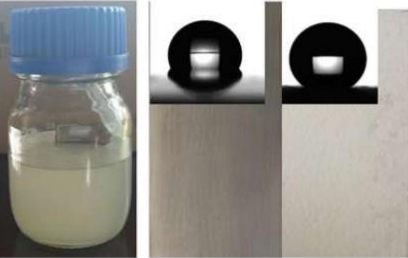